Xilinx IP - Frame Buffer Read Example
Device name: Zybo. (Zynq-7000)
Vivado Version: 2020.2.
Goal: To write unique frames in the DDR3 memory capacity and read-out frame by frame as well as display the frames with a variable refresh rate. Real goal is the avoidance of the painful VDMA IP and using a lighter IP.
Github repo: https://github.com/rappysaha/FrameBufferRead.git
How to regenerate the project
Step 1: Download the Git repo in your local directory.
Step 2: Vivado 2020.2 should be installed and Zybo boardfiles should be in place. Please follow the guide from Digilent to install the board files perfectly.
Step3: Open the vivado go to the Tcl console. cd to the saved location of the github repo
cd <saved location of git repo>/FrameBufferRead/Prj_FBR/
press Enter
source ./FBR.tcl
vivado will regenerate the project.
Step4: Synthesize, Implement and generate bit stream in the Vivado.
Step5: Export the hardware, .xsa file with bitstream included.
Step6: Setup a Application project with .xsa file that has be exported. Again, you can follow the guide from the Digilent.
Step7: Copy all the src files from the
<saved location git repo>/FrameBufferRead/Prj_FBR/VitisSrcFIles/.
Step8: Build the project and connect the Zybo Board. Open the terminal with baudrate 115200. Connect a VGA or HDMI display.
Step9: Lunch application project in the Zybo by download the .elf file and .bit file in the Zynq Soc. Follow the Digilent guideline here again.
Successfully, you are running the project.
IP Schematic Design
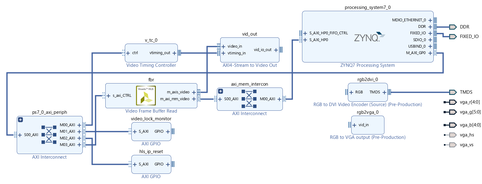
Required IPs:
- Zynq7 Processing System: After block automation, the
S_AXI_HP0interface was enabled to read out the data from DDR3. The Pl to Ps interrupt was also enabled. The required clocks were also generated from the Zynq also. Three different clocks can be required here.
- M_AXI_GPIO clock: 100 MHz (default).
- S_AXI_HP0 clock: 200MHz. Depends how fast do you want to read out the video. It can be same as M_AXI_GPIO clock, if we do not have any specific read out requirements.
- Clock for VGA and DVI Ips: 74.25 MHz. Depends on output video resolution, in our case it is 720p.

- M_AXI_GPIO clock: 100 MHz (default).
- Frame Buffer Read IP: This IP is used to read out frames from the DDR3.
- AXI4 Stream to Video Out IP: This IP helps to convert AXI4 stream data to the RGB data that will be used by VGA or DVI IP. It can bridge between read out speed and display frequency.
- The Video Timing Controller: This IP will generate the required timing signals for the desired display resolution.
- Video Lock Monitor IP: This has input from the AXI4 Stream to Video Out IP. The locked signal from the AXI4 Stream to Video Out IP is monitored by the Video Lock Monitor IP.
- HLS Reset IP: This will help to reset the Frame Buffer Read IP asynchronously for any time by software.
- Rgb2vga IP: By this we can connect a VGA display for the output.
- Rgb2Dvi IP: By this IP we can connect a HDMI display for the output.
Vitis Part
After regenerating the project if we move to the Vitis part. In the Vitis we took the bare metal approach. Following description will be helpful to understand the steps of the main.c file.
Step 1: Reset the FBR IP,
gpio_hlsIpReset = (uint32_t *)XPAR_HLS_IP_RESET_BASEADDR;
*gpio_hlsIpReset = 1;
Step 2: Setting up the interrupts and connect it with the ScuGic. Setting up interrupt can be quite confusing some time. If you are using Zynq device, this presentation explains the matter quite clearly and it is really easy to follow. My Approach is more or less similar to the presentation.
Status = SetupInterrupts(ScuGic_ID, FBR_INTR_ID, &intc, &frmbufrd);
if (Status == XST_FAILURE)
{
    xil_printf("ERROR:: Interrupt Setup Failed\r\n");
    xil_printf("ERROR:: Test could not be completed\r\n");
    return (1);
}
Step 3: Initialize rest of the IPs in your design. We have initialized here video timing controller, FBR and GPIO that is used for check out the locking of the video output.
Status = DriverInit(VTC_ID, FBR_ID, GPIO_ID, &vtc, &frmbufrd, &vmon);
if (Status != XST_SUCCESS)
{
    xil_printf("ERROR:: Driver Initialization Failed\r\n");
    xil_printf("ERROR:: Test could not be completed\r\n");
    return (1);
}
Step 4: Setting up the callback functions. Most important part of this application. Here, we have connected a function namned XVFrameBufferCallback() whenever the there is and interrupt from the FBR IP. Whenever we go to that function the required variables can be accessed via frmbufrd structure.
XVFrmbufRd_SetCallback(&frmbufrd, XVFRMBUFRD_HANDLER_DONE, XVFrameBufferCallback,
                           (void *)&frmbufrd);
Step 5: Setting up the parameters to configure the Vtc the FBR in the next step. This the place where #include "xvidc.h" header file comes handy. Thanks to Xilinx for providing such a wonderful header file to configure the IPs related to the video or image processing.
VidStream.PixPerClk = frmbufrd.FrmbufRd.Config.PixPerClk;
VidStream.ColorDepth = frmbufrd.FrmbufRd.Config.MaxDataWidth;

// Get video format to test
Cfmt = ColorFormats[0].MemFormat;
VidStream.ColorFormatId = ColorFormats[0].StreamFormat;

// Get mode to test
VidStream.VmId = OutputModes[0];

// Validate testcase format and mode -- Do not need
// Get mode timing parameters
TimingPtr = XVidC_GetTimingInfo(VidStream.VmId);
VidStream.Timing = *TimingPtr;
VidStream.FrameRate = XVidC_GetFrameRate(VidStream.VmId);
Step 6: At this point, we will write three unique frames to the DDR3 those read out later by FBR IP at different refresh rate and will be displayed at the monitor.
// write memory frame by frame
frmPtr = (uint8_t *)XVFRMBUFRD_BUFFER_BASEADDR;
Demo1Frame(0xFE, 0x00, 0x00);
frmPtr = (uint8_t *)(XVFRMBUFRD_BUFFER_BASEADDR + 0x2A3000);
Demo1Frame(0x00, 0xFE, 0x00);
frmPtr = (uint8_t *)(XVFRMBUFRD_BUFFER_BASEADDR + 0x2A3000 + 0x2A3000);
Demo1Frame(0x00, 0x00, 0xFE);
Step 7: Configure the vtc according to our expected output video resolution. Then configure the FBR to tell the starting address of the Frame and also notify the FBR how the pixel data is written in the memory. FrameBuffer read IP will be start after that.
// Configure VTC
ConfigVtc(&VidStream);
// Configure Frame Buffer
ConfigFrmbuf(DEMO_STRIDE, Cfmt, &VidStream);
Step 8: Printing the menu in the terminal and waiting for the user input from the terminal.
PrintMenu();
//go to the while loop
DemoRun();
Here is the video demo of the project: