Zed Board HDMI Out Demo
Device name: ZED Board. (Zynq-7000)
Vivado Version: 2020.2.
Goal: Test the Zed board HDMI port.
Github repo: https://github.com/rappysaha/Zed_HDMI_OUT.git
How to regenerate the project
Step 1: Download the Git repo in your local directory.
Step 2: Vivado 2020.2 should be installed and Zed board boardfiles should be in place. Please follow the guide from Digilent to install the board files perfectly. For this project the license for video test pattern generator IP will be required. Evaluation license will work also.
Step3: Open the vivado go to the Tcl console. cd to the saved location of the github repo
cd <saved location of git repo>/Zed_HDMI_OUT/
press Enter
source ./create_proj.tcl
vivado will regenerate the project.
Step4: Synthesize, Implement and generate bit stream in the Vivado.
Step5: Export the hardware, .xsa file with bitstream included.
Step6: Setup a Application project with .xsa file that has be exported. Again, you can follow the guide from the Digilent.
Step7: Copy all the src files from the
<saved location git repo>/Zed_HDMI_OUT/vitisSrcFile/.
Step8: Build the project and connect the Zed Board. Open the terminal with baudrate 115200. Connect a HDMI display.
Step9: Lunch application project in the Zed by download the .elf file and .bit file in the Zynq Soc. Follow the Digilent guideline here again.
Successfully, you are running the project.
NB: During the synthesis, if you have any warning similar to the following warning, reducing the path length of the project will help.
WARNING: [IP_Flow 19-4318] IP-XACT file does not exist: d:/Test/Zed_HDMI_OUT/proj_1/proj_1.srcs/sources_1/bd/ZED_Hdmi_Out/ip/ZED_Hdmi_Out_v_tpg_0_0/ZED_Hdmi_Out_v_tpg_0_0.xml. It will be created.
IP Schematic Design
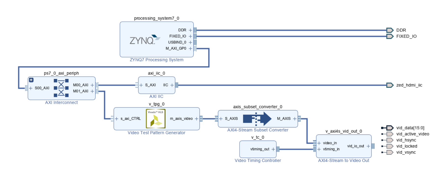
Required IPs:
- Zynq7 Processing System: It will help to connect Axi based pripherall to control the parameters from the OS side. In our case, AXI based IIC controller and video Test pattern generator parameters will be controlled by the Zynq processing system in the OS side.
- AXI IIC IP: This I2C IP is the main requirement for the Zed board HDMI configuration. The I2C IP is required to configure the ADV7511 chip. We need to supply the 16-bit video data to the ADV7511 since it will accept only 16-bit from the FPGA. In the XDC file of the Zed Board, we can see the 16-bit data connection for the HDMI part.
- Video Test Pattern Generator IP: The test pattern generator will generate 720p test pattern. The clock of the video timing controller will depend on the selected resolution.
- Video Timing Controller: The timing controller for this example is in the native mode to keep the example as simple as possible.
- AXI4 Stream to Video Out IP: Video Out IP will be configured in the independent mode. The video out clock will be same as the video timing controller clock. The output of the Video out IP will be connected to the ADV7511 input. In this example, we are not considering audio output via HDMI.
Vitis Part
After regenerating the project, if we move to the Vitis part. In the Vitis, we took the bare metal approach. Following description will be helpful to understand the steps of the main.c file.
Step 1: Initialize the AXI IIC interface
Status = zed_iic_axi_init( &iic, "ZED HDMI I2C Controller",IIC_BASEADDR);

if (Status != 1) {
    xil_printf( "ERROR : Failed to initialize IIC driver\n\r" );
    return -1;
}
xil_printf("IIC initialization Successful\n");
Step 2: Hot plug detection system. It is not an interrupt based system, usually hot plug detection system should be an interrupt based system. Therefore, it will detect the HPD signal for once.
while(!mon_conn)
{
    mon_conn = check_hdmi_hpd_status(&iic, 0x39);
    if (mon_conn)
    {
        xil_printf("HDMI Connected\n");
    }
    else
    {
        xil_printf("HDMI NOT - Connected\n");
    }
    sleep(2);
}
Step 3: Configuring particular registers of the ADV7511 via I2C. These are the predefined registers, defined by the Avnet.
HDMI_config(&iic);
xil_printf("HDMI Setup Complete!\r\n");
Step 4: Initializing test pattern generator (TPG), configuring TPG and Start TPG
Status = XV_tpg_Initialize(&tpg, TPG_ID);
if(Status!= XST_SUCCESS)
{
    xil_printf("TPG configuration failed\r\n");
    return(XST_FAILURE);
}
// Set Resolution to 1280x720
XV_tpg_Set_height(&tpg, 720);
XV_tpg_Set_width(&tpg, 1280);

// Set Color Space to YUV422
XV_tpg_Set_colorFormat(&tpg, 0x2);

XV_tpg_Set_bckgndId(&tpg, XTPG_BKGND_COLOR_BARS);
// Set	 Overlay to moving box
// Set the size of the box
XV_tpg_Set_boxSize(&tpg, 50);
// Set the speed of the box
XV_tpg_Set_motionSpeed(&tpg, 5);
// Enable the moving box
XV_tpg_Set_ovrlayId(&tpg, 1);
//Start the TPG
XV_tpg_EnableAutoRestart(&tpg);
XV_tpg_Start(&tpg);
The LED 0 of the Zed board will be turned on when video output will be locked. At the end, no specific HDMI IP is required for the Zed Board HDMI since ADV7511 is doing most of the work. On the other hand, board like Zybo do not have this ADV7511 chip, therefore, RGB2DVI IP from Digilent was quite helpful.
Demo
The Zed Board connection:
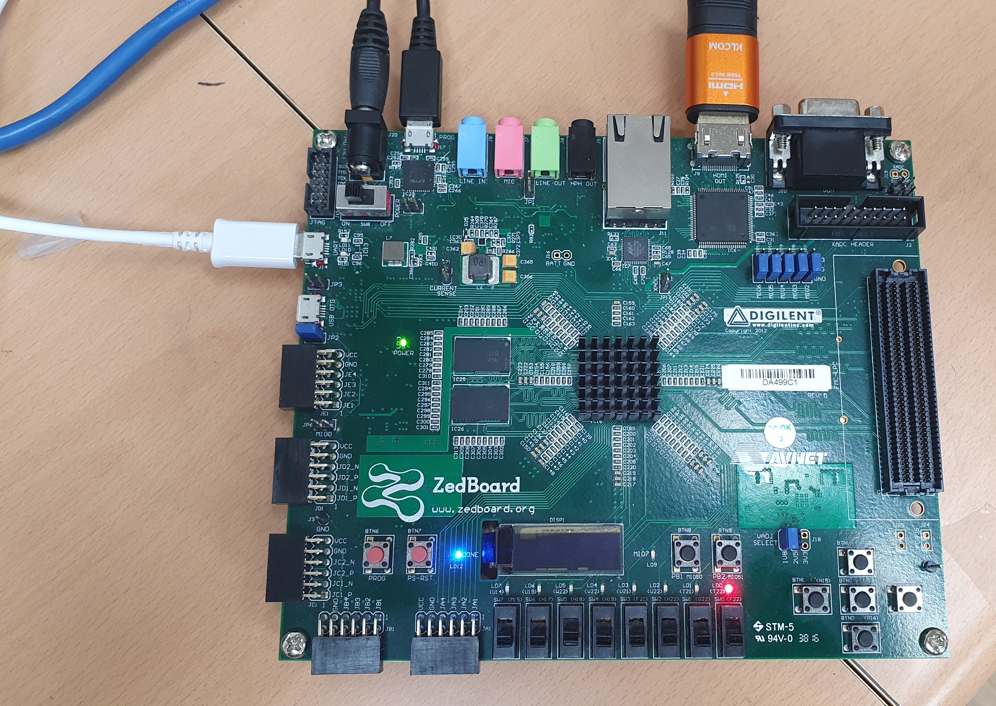
Here is the video demo of the project:
References:
The project was created by the help of the following links.
The above mentioned series targeted ZC702 board while this project is all about Zed board. Lots of similarities but simple difference is there and that is also discussed in the Xilinx forum by the author of the above series. Depending on this discussion this project was build. There is slight modification in HDMI configuration.